🔐 Lock in effortless security and elevate your gate game.
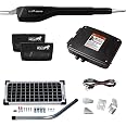
The Automatic Electric Gate Lock by X X-HOUSE is a robust, waterproof stainless steel locking system designed for swing gates. Operating on 12-24V AC/DC, it features a low-force 1 lb engagement mechanism that reduces strain on your gate opener, extending its lifespan. Compatible with most gate openers, it automatically locks and unlocks with gate activation, providing enhanced security especially in windy conditions or for pet owners. The package includes essential hardware and two manual keys for emergency access.


| Brand | X X-HOUSE |
| Mounting Type | Floor Mount |
| Material | Stainless Steel |
| Color | Electric Gate Lock |
| Style | Modern |
| Number of Pieces | 1 |
| Manufacturer | GIANT |
| Item Weight | 5.39 pounds |
| Product Dimensions | 8.39 x 4.02 x 2.09 inches |
| Size | Electric Gate Lock |
| Pattern | Solid |
| Item Package Quantity | 1 |
| Special Features | Waterproof |
| Batteries Included? | No |
| Batteries Required? | No |
K**.
It WILL work with Ghost Controls - here is how I finally got it working
I have a dual actuator Ghost gate opener. I could not get the board included with the lock to work correctly. I think because the controller initially outputs a small but increasing voltage on the red (or black) wire to get a smooth start to the opener until it reaches full speed at 12V, the initial voltage applied didn't seem to be high enough for the ghost board to "think" that the lock was open. I have a replacement main control board that Ghost shipped me when mine failed and I think they changed the programming on the newer boards. With the old board, I could get the lock to work by just jumping the positive (+) terminal to the signal (S) terminal on the ghost board, but with the new one, it would not work that way. My theory is that the controller is looking for a miniscule delay from the time the lock is actuated until the signal returns and that is why the jumper didn't work anymore. I say this because with the board jumpered, the opener would not operate, but by manually shorting + to S right after pushing the button, the opener would operate. This short delay meant that a time delay relay (TDR) should be the fix.I initially tried a hardware driven TDR, but when the lock actuated, the relay would flutter on and off multiple times per second and I was afraid that it would wear out in a week, so what I wound up doing was installing an electronic timer that had a delay function. I bought this: https://www.amazon.com/dp/B083HN673G?psc=1&ref=ppx_yo2ov_dt_b_product_detailsIt has been rock solid so far and because it is completely electronic, it does not suffer from the flutter that the other relay had. It is possible that I got a bad relay, but it worked fine with other setups. Yes, it adds $35 to the cost of the setup, but it is still $100 cheaper than the ghost lock. I have attached an image showing how I wired the timer. I used function 1 and set the delay to 10/30ths (1/3) of a secondSorry for the long explanation, but I tried many different combinations (including the other ones listed on this page) and this was the only way I was finally able to get the lock to work reliably with my ghost control system
J**C
GHOST CONTROLS INSTALLATION WITH PHOTOS + HOW TO SECURE LOCK
As indicated in my detailed instructions, the process to program this piece of junk can be done, however, the time expended to do so is a waste of time because the lock will become defective after it is used for a month or so.In my case, the lock worked flawlessly for about two months, teeth would quickly disengage when activated, then the teeth would not disengage even though it was receiving power. then worked intermittently for a month. Worked again. Then, a month or so later would work only when it wanted to. It is time to trash it.I tried to contact the seller, but that was impossible. Hopefully, Amazon will step in and get me a refund. If not, I will never buy anything on Amazon again because a few other items I purchased recently are also junk. From this experience it is clear that you get what you pay for, buy cheaply made junk, then that is what you get. As indicated in my detailed instructions, the process to program this piece of junkThe instructions provided by the seller were useless, (so was the information provided by the buyers who posted installation data) so that should have been a warning to return the lock, but I decided to spend several hours trying to figure out how to install it so it would work. I almost gave up, but perseverance paid off. (The only problem I encountered five months after purchase was the lock would malfunction (not open) when the outside temp hit above 105% which occasionally occurs here in the desert. Other than that, the lock works fine so.I purchased this item on Amazon, the seller was/is EZY Control, aka X-X House.On or about September 1, 2022, less than three months after installation, the gate lock became defective, that is the teeth would not engage/release when activated, thus preventing the gate from opening.I was hoping there was a way to contact the seller for assistance, however, there is no way to do that, si I to contact Amazon and was told they would issue a refund.In retrospect I should not have been so penurious and just purchased a Ghost Controls Zombie lock, but I was trying to save a buck. As I justified the purchase to my wife, this lock was 1/2 the price of a Zombie lock. Now the wife is laughing at me as I spend the time removing it.END OF COMPLAINT. For those of you who disregard my experience, I am leaving my instructions how to quickly install the gate lock. Raad it, look at the photos as it will save you a lot of time.For the reading challenged, I posted clear and concise photos showing how to make the requisiteconnections to enable this lock to work on your GS gate opener lickity split, so, just skip the narrative and look at the photos. I tried to post the photos in order of use, however, Amazon changed the sequence order so I numbered them 1-7 left to right.Moreover, if you want to use the lock as designed, to securely open and close the gate while inside your car, without having to exit to manually lock the gate, I am providing information and guidance to help in that regard. Photos are also posted.To begin, to ensure the Ghost Controls control box reflected in the photos I posted is the same model as yours (most GC control boxes are the same or very similar), you may find it wise to take a couple minutes to read the following, then compare the photos to your specific model.I took the time to post these instructions & photos because as another purchaser pointed out, whoever posted the 3 photos of the installation process for the GC (which I relied on to my detriment) must have done so with the goal of showing how not to attach the wires because the diagram is WRONG!! (Those photos may be for a GC Zombie lock which will NOT work for this lock) The Zombie Lock, which may be easier to connect because it is a GC, however, it costs twice as muchFollowing the information set forth herein will make the task almost as easy as connecting a GC Zombie lock.Threre is another post, long and rambling provided by another purchaser which was accurate, I found it confusing, having to read it several times.Finally, after I installed the lock I discovered if I want to securely close and open the gate from my car I would have to replace the clevis pin that came with the lock with one designed for a lock. I explained in detail below how to accomplish that task.Hopefully the following information will be helpful. To avoid confusion, I will begin by identifying the model I installed for my daughter: HDP1, Manor Series, single column. (Costco HDSK)HERE ARE THE INSTRUCTIONS:1. Don't waste time contacting the seller unless you speak Chinese.2. Parts needed: 1) 12 inches of red 16/8 AWG wire; 2) 12" of black 18/18 AWG wire; 3) 12" of blue, or any color 16/18 AWG wire; 4) three (3) electrical connectors; 5) locking clevis pin.3. Open the GC control box and look (bottom center) for one black and one red wire coming from the battery box to the control box. Those two wires are connected to two wires in the control box. (right hand side) They are push and pull, so easy to disengage. (see 6-7)4. Disconnect both the red and black wires that are connected to the two blue push and pull connectors. Use two (2 red connectors) of the electrical wire connectors to connect the wires, then snap the battery/control box wires together. You now have four (4) dangling wires, one red and one black. (See photos 6-7)5. Fetch the small control board DS33A that came with the lock and connect the red wire to the NO (4) terminal. (The terminals are numbered 1-5)(See photos 3, 5)6. Connect the black wire to GND terminal number 2. (See photos 3, 5)7. I am next presuming you have run the lock wires, one red, one blue, up through the GC control box. If not, do that next. Easy peasy.8. Connect either wire to the CM (5) terminal on the small Control Board DS33A. (see photos 3, 5)9. Connect the other wire to GND terminal number 3. (see photos 3, 5)10. Fetch about 12" of 16/18 gauge wire, blue, green, purple, any color except red or black and connect it to the number 1 (VCC) terminal on the DS331 lock control board. (see photos 3, 5)11. To check to insure you made the correct connections, take the wire described in No 10 above and run it up to the battery box and quickly touch the positive terminal. If you hear a click, then go to the next final step. If no click, follow the instructions again.12. Just about done. Look for the 1st Operator connection in the GC control box. (near bottom on the far right hand side) Depending upon whether you have a push or pull opener will determine where you attach the No. 1 wire VCC. (see above No 10)(see photo 2)13. If you have a push operator, fetch the electrical wire connector and splice it to the VCC wire to the black terminal. If you have a pull operator, tie into the red terminal. (See photo 2)if you followed the instructions, you are done.SECURING THE LOCK:As others have pointed out, when the gate is closed, if not locked with a key, (which would be a pain in the ...) every time you opened and closed the gate you would have to fetch a key and lock it to prevent intruders.What I initially did was purchase a stainless steel clevis pin ($9.00) at Ace Hardware, bored out one of the holes to make it larger to accommodate the combo lock, (Brinks model 171-30051) then slid the lock inside. I did not like the way the lock sat in the slot so I bought a GC locking clevis pin on Amazon. (See photos reflecting different clevis pins)(see photo 1)The GC pin was wider than the top and bottom clevis pion slots in the lock mounting bracket so I grabbed my Harbor Freight rotary tool and bore out the slots in the bracket by about 1/32 of an inch. (see photo 4)DONE
Trustpilot
3 weeks ago
2 months ago