🔧 Connect with Confidence: Elevate your automotive game!
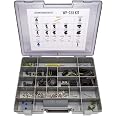
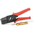
The Delphi Weather Pack Connector Kit WP-155 is a comprehensive 155-piece set of sealed weatherproof automotive electrical connectors, designed for 20-12 gauge applications. This kit includes high-quality male and female housings, crimp terminals, and a specialized removal tool, all housed in a portable carrying case for easy field repairs.
| Manufacturer | CustomConnectorKits |
| Brand | DELPHIKITS |
| Model | WP-155 |
| Item Weight | 3 pounds |
| Product Dimensions | 16 x 12 x 3 inches |
| Item model number | WP-155 |
| Is Discontinued By Manufacturer | No |
| Manufacturer Part Number | WP-155 |
| OEM Part Number | 12015791 12010996 12015792 12010973 12015793 12010717 12015797 12010974 12015799 12010975 12089040 12089188 12015323 12124582 12124580 12010293 12124587 12124581 12015193 12010300 12014012 |
| Voltage | 12 Volts |
R**Y
Best water proof/Automotive connectors
This is the second kit I have bought from this company and its worth every penny. The connectors and pins are solid. The rubber pieces that go over the wire are plenty. I would recommend these connectors for building wiring that will be exposed to the elements.
B**H
Nice kit, good quality
Nice kit, good quality.using it in the ls engine swap in a early 70's corvette , would buy again, and have bought add ons to this kit to finish work
B**H
Nice kit
This is a nice kit, but expensive. Oh well, quality comes at a price. It works well and gives you the needed flexibility to install and repair connectors.
A**Y
Great and economical
I replaced all the broken/melted connectors in my car with these. Great for connecting wires. Better for making the girls go OOO
B**D
Great Quality!
I have a Can-Am Renegade and it has alot of Delphi plugs on it, I'd assume anything Can-Am does, so this comes in handy when adding accessories.
L**S
weatherpack
Came fast and in good shape. Have not had a chance to use the connectors, however, they look like they would work good.
J**T
Instructions.
I am cutting and pasting the excellent instructions written by this guy. Don't thank me thank him. http://www.amazon.com/gp/pdp/profile/AYAXWDXO97UKG/ref=cm_cr_dp_pdp His review appears http://www.amazon.com/review/R121I2P7UN0LRM/ref=cm_cr_dp_title?ie=UTF8&ASIN=B005AZWPUI&channel=detail-glance&nodeID=15684181&store=automotive1. Determine which seal fits snugly, but not overly tight around the insulation on your wire. Set aside.2. Strip 1/4 inch from the wire. No more.3. Place the seal on the wire insulation with the narrow end toward the stripped end of wire. When correctly placed, the seal will match up to the end of the insulation where it was cut for stripping.4. Select either a sleeve or a pin, depending on which side of the connection you are building. The sleeves are used with the connector piece that has the factory-installed connector seal. The pins are used with the connector piece that the connector seal slides into.5. For the sleeve/pin, there are what look like three crimp regions. The large crimp is for the seal. The next, smaller crimp (with two or three tabs) is for the bare wire. The next "crimp" is not a crimp, don't hurt it (I made this mistake, this one helps hold the pin/sleeve in the connector shell).6. We will crimp twice. Our first crimp is for the wire. Using the supplied pliers, place the wire crimp region that you identified earlier (with two or three tabs) into slot three or four (depending on the size wire you are crimping, I haven't found a need for the smaller slots, but maybe....) You can always start with slot 4 and then use 3 or 2 if you think you need more crimp. One side of the crimper on the pliers is round and the other is like a 3 or w or lower-case omega. The open end of the crimp region on the pin/sleeve should face the "w" part of the crimper. If you close the pliers down ever so slightly, the pliers will hold the pin/sleeve while you do other things. Also note that the crimp region is sized exactly the same width as the pliers, thus you can crimp the wire in only one step.7. Now, insert your bare stripped wire into the pin/sleeve where the crimp will occur. Do not insert too far. Since you've previously placed the seal flush with the end of the insulation, that provides a guide of where you want to put the wire. This is why we only stripped off 1/4 inch in the second step. Compress the crimp with the pliers. I've got pretty strong hands and I didn't damage anything with unmitigated pressure, so have at it.8. Make sure that the seal is all the way up to its crimp tabs. The tabs are large and should be prepared to wrap around the narrow part of the gasket. Place these tabs into slot 5 of the crimper. Again, there are two sides. The open side of the tabs should face the side of the crimper that has long sides. Note that each zone of the crimper has a long side and a short side. The zones alternate, one has the long side on the right (as you look at the crimper) and the next has the long side on the left. If you turn the crimper over, the sides change from right to left and vice versa (I know, this is obvious, but it took me decades to get used to that, and I'm not sure that I still don't get surprised when it happens). when closed, zone 5 makes a circle that is exactly the size of the tabs closed around the seal. So now, we crimp. Make sure the seal is properly positioned between its tabs, then place the pin/sleeve into the crimper (squeeze the tabs together with your fingers if they are spread too far), then compress until the tabs are formed into a circle. I'm pretty sure it's a bad idea to over-squeeze here. If the seal was selected correctly to fit the insulation on the wire and the crimp was done right, the gasket will be firmly held in place.A SIDE NOTE: This kit doesn't have the right seals for 24 gauge wire, so either just live with it or find the right seals.9. We are almost there. Note that on the connector shell, there are letters, (A, B, C, ...) for each pin/sleeve location. These are matched between male and female connectors. By the way, Delphi calls the connector shell with the factory-installed seal the female side and they call the other connector shell the male side. The reason is that the SLEEVE connector goes into the female shell and the PIN connector goes into the male shell. For my part, since the female shell goes into the male shell, I get confused. Just remember that the sleeves go into the connector shell that has the factory-installed seal.10. Push the connector into the shell. Which end? Note that the shell has a fold down cover. This "strain relief" holds the seals into the shell so that the shell is more robust. By looking at the shell, you can quickly determine which end of the shell will get this cover. That's the end you insert into. However, this is a well-designed product. I inserted one the wrong way, pushed it in, realized my mistake, and then it just pulled out. No muss.11. When the connector is properly pushed in, it will click. The seal will be flush or recessed in the connector shell.12. Once all the connectors are pushed into the shell, fold down the strain relief and click the two tabs closed. Your connector is now complete.13. Build the mating connector.14. Now that the two halves are complete, they can be pushed together. Note that there's a plastic tab that holds the connectors together. This clicks into place.15. The connectors can be separated without tools. To do so, gently pry the locking tab up from the connector shell while pulling the connectors apart. When they have barely moved relative to each other, you can stop prying the tab up and just pull the connectors the rest of the way apart.
B**H
Great base kit
Plenty of pins/connectors for a base kit, refill options available and listed on the case for easy location
Trustpilot
1 day ago
1 week ago