Description
🔵 Illuminate your projects with clarity and ease — the ultimate 16x2 LCD duo for pros!
- UNIVERSAL COMPATIBILITY - Designed to work flawlessly with Raspberry Pi and Arduino, perfect for displaying real-time data like clocks, temperature, and humidity.
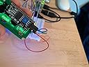
- PLUG PLAY I 2 C INTERFACE - Simplify your wiring with the I2C serial interface adapter—just 4 pins (VCC, GND, SDA, SCL) for seamless Raspberry Pi or Arduino integration.
- RELIABLE READY FOR MAKERS - Backed by a 12-month warranty and satisfaction guarantee, this 2-pack ensures you never run out of display power for your next big idea.
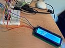
- CRYSTAL CLEAR BLUE BACKLIGHT - Experience sharp, easy-to-read 2 lines x 16 characters display with vibrant blue backlight that stands out in any project setup.
- CUSTOMIZABLE CONTRAST BRIGHTNESS - Fine-tune your display visibility with an adjustable potentiometer and backlight header for optimal viewing in any lighting condition.
The JANSANE 16x2 1602 LCD Display Screen with I2C Module is a dual-pack blue backlit LCD designed for Raspberry Pi and Arduino users. Featuring a 2-line by 16-character display controlled by the HD44780 chipset, it offers easy I2C serial communication with just four pins, adjustable contrast, and a 5V operating voltage. Ideal for real-time data display like clocks and sensors, it comes with a 12-month warranty and satisfaction guarantee, making it a reliable choice for professional makers and developers.