Desert Online General Trading LLC
Dubai, United Arab Emirates
Desert Online General Trading LLC
Dubai, United Arab Emirates


📡 Elevate your IoT game with wireless freedom that commands attention!
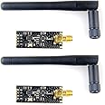
The MakerFocus NRF24L01+PA+LNA wireless module is a compact, Arduino-compatible 2.4GHz transceiver featuring an impressive 800+ meter range, 5V tolerant SPI inputs, and configurable data rates up to 2Mbps. Equipped with integrated power and low-noise amplifiers, it ensures robust, clear communication with smart auto-acknowledge and retransmit functions for reliable performance in your wireless projects.
| Brand | MakerFocus |
| Product Dimensions | 10.6 x 7.8 x 0.32 cm; 18.14 g |
| Item model number | 4328612760 |
| Manufacturer | MakerFocus |
| Color | Black 2pcs |
| Voltage | 5 Volts |
| Are Batteries Included | No |
| Item Weight | 18.1 g |
M**A
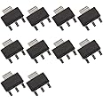
Use a 10-220uf Cap across the power leads to function correctly.
I built 12 units that utilized this NRF24L01+PA+LNA. A couple of things you need to know. Add the cap around the power leads of the unit like the attached picture. If you don't, it will not work. Also, when testing, these units are powerful and sensitive with a range of 800-1000 meters. So testing side by side may not work correctly even at the MIN power setting. Taking the unit 20 to 30 foot away with a couple of walls the way will do it. Best to use separate power supplies for the SBC such as nano, pro mini or Mega, and 3.3-3.6v for the NRF24L01+ PA+LNA. Most Arduino's can not source enough current from their 3.3V pin. KD0ZW
E**N
Beware faulty pins. Adapter recommended. Great module otherwise. (Tips included)
When I got these, I immediately jumped into testing them. I had my arduinos set up on two separate breadboards to do a little testing with the interface. I'm fairly experienced with arduino, so this shouldn't have been a problem at all if the hardware functioned properly, but because the connections on the pins were loose, the transmission/reception on one of the boards became choppy, and at one point stopped all together. This turned into a multiple hour ordeal of troubleshooting and trying to figure out if my boards were shot, or if the receivers were faulty. Once I found the fault, I was able to fix the problematic pins and create a really stable connection. If you buy the voltage regulating adapter and get a functioning unit, this thing will work beautifully.TIPS:One thing you may notice when interfacing with these through tmrh20's RF24 library, is that it does not recognize the function:radio.setPALevel()this is because the function name exists in the RF24.cpp file, but is not being referenced in the keywords.txt file located in the library. To fix this, simply open the file in word pad and save over the file after adding the following line:setPALevel KEYWORD2
A**R
Unlucky or bad quality control
I must be one of the unlucky customers with this product. I have a working program (Ping Pong) to test the RF24's which works flawlessly for the model down version. When I replaced the models with this one, things didn't work. I put some distance between them thinking they were too close together, and also tried setting the strength to MIN, hoping to help the distance issue. Nothing.. Then I found the issue, upon inspection of these, there were all sorts of poor soldering. One of three worked. 2 of them had multiple soldering issues where the SMD's weren't even remotely close to be seated correctly (not even on their contact pads). Whoever solders and inspects these things needs to have their eyes checked or be given breaks so they'll actually pay attention when they're soldering..
M**.
Incorrect pin map
I've been using these boards for a bit now for a MySensors network that needed a bit more range than the board trace antennas would offer, and they seem to be doing the job. The range improved to at least as far as I've ever needed, and things seem as stable as with any other NRF24 module I've used.Update: Makerfocus contacted me about this review and explained that a bad batch from a supplier had made it past their QA with the incorrect silkscreening, and showed boards from their new batch that seemed to be marked correctly. They also offered to send me a new board to make up for the hassle. Since they took the time to follow up and document that the problem has been resolved, I've updated the review score to reflect that. Do still check to make sure about the below concerns if you've recently bought these or are planning to buy these around the time of posting this review. My only remaining issues with these are the price and the board finish, but both seem to be in line with what other vendors offer for the same product.---The build quality on these is terrible. The PCB edges haven't been even lightly sanded so you're gonna cut yourself on these boards if you mess around with them for too long, but worst of all is that the silkscreening on the bottom side of the board is reversed! The top side (chip side) silkscreen has the ground pin correctly squared off, but on the bottom side the pinout text is flipped vertically so that the pin connected to ground is labeled MISO. I was worried that it was simply a different pinout from all the other NRF24 modules and power regulator breakout boards, but I toned it out, and at least on my board the physical pinout is standard despite the incorrect pin map on the back of the board.If you get these and you're in doubt about how they're wired, check the NRF24 chip on the board (it's the larger one closest to the pin connectors) and find the dot at the corner edge. The dot marks the upper left corner of the chip. With that orientation, the uppermost pin on the left side of the chip is CE, and the leftmost pin on the upper side of the chip is ground. You can tone those to the pins on the board to verify whether or not the screening is reversed. If you have a regulator board, you can connect the NRF24 module and tone the aforementioned pins on the chip against the CE and GND pins on the regulator board.
P**.
Works well, good range for my use (inside house through walls and ceiling). Trickier to get to work.
I have 2 types: the nrf24l01+ with antenna and the AS01-ML01Quick test, they work as advertised. I did a small range test in the house, did not get any drop outs (i estimate about 300 ft).I used 1 with antenna and 1 with PCB antenna and already got improved range.I also tested a set with regular PCB board-antenna and they drop at the far end of the house, so this is an improvement in range.I also tried to get them really very close to each other without issues.They have the same standard (8 pin) connections so if you use headers you can simply swap them outHOWEVER... i have some strange experiences with the external antenna ones vs. the pcb antenna: i have several circuits and build a simple receiver and transmitter for testing these modules. I found that the PCB ones always work, the ones with antenna are trickier. They work fine in some circuits and not in others. Sometimes they only work when i touch the antenna or some of the pins with my hands and i have not figured out why it works fine in one cricuit and not in another. I think it's important to keep the (SPI) connections as short as possible, i also use a capacitor over gnd/Vcc (i tried moving from 100nF to 10uF but no change in behavior). In my case the antenna did not work when it points up 90 degrees (the obvious first one to try) but works great at some other angles. So all in all a bit finicky.Update: some people report better reliability if the module is housed in a metal case or even foil. Just be careful about short circuit
ترست بايلوت
منذ 3 أسابيع
منذ أسبوع